CNC Lathe Machining Process: Setup, Steps, and Quality Checks
A CNC lathe machining process uses a programmed machine to turn a workpiece while cutting tools remove material to create the required shape and dimensions. It is commonly used to manufacture cylindrical components, shafts, sleeves, threaded parts, bushings and other metal components.
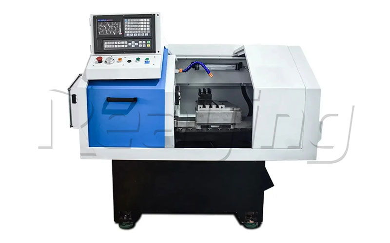
Achieving consistent results requires more than selecting a CNC lathe. Workpiece clamping, tool selection, programming, cutting parameters and dimensional inspection all influence the final part. Understanding each step helps manufacturers plan production more effectively and choose equipment that matches their actual machining requirements.
What Is the CNC Lathe Machining Process?
In a typical CNC turning operation, the workpiece rotates while a cutting tool moves along programmed paths. The machine follows the instructions of its CNC control system to remove material from the workpiece.
Depending on the machine configuration, tooling and program, CNC lathes can perform operations such as external turning, facing, boring, grooving and threading. Not every machine or tool setup supports every operation, so the required processes should be confirmed before production.
The objective is to produce a component that matches the engineering drawing, including its dimensions, specified tolerances and surface finish requirements.
Step-by-Step CNC Lathe Machining Process
1. Review the Drawing and Workpiece Requirements
Before machining begins, review the part drawing and identify the features that must be produced. Important details include the material, raw workpiece dimensions, finished dimensions, tolerances, threads, grooves, hole requirements and expected surface finish.
Production quantity is also important. A one-off prototype may require a different setup strategy from a recurring production order. Confirming these requirements first helps avoid choosing unsuitable tooling or machine configurations.
2. Select the Machine and Workholding Method
The machine must provide sufficient working capacity for the part. Check its maximum turning diameter, available machining length, spindle bore and other relevant specifications against the workpiece.
Select a suitable clamping method, such as a collet or chuck, according to the part’s shape, dimensions and required clamping force. The workpiece must be held securely and positioned appropriately throughout machining.
Long or slender components may require additional support, depending on their dimensions and the machining conditions. Confirm that the selected machine and workholding arrangement are suitable for the actual job.
3. Choose the Cutting Tools
Tool selection depends on the workpiece material, operation, required finish and cutting conditions. Different inserts and tool geometries may be needed for roughing, finishing, threading, grooving or boring.
Before running the program, check that the tools are installed securely and that their offsets and positions are correct. Confirm tool clearance and make sure the programmed movements are compatible with the machine configuration.
Tool wear should also be considered. A worn or damaged cutting edge can affect surface quality, dimensions and process stability.
4. Prepare the CNC Program and Cutting Parameters
The CNC program defines the tool movements and machining sequence. Depending on the part and machine, it may include multiple passes, facing, turning, grooves or thread-cutting cycles.
Cutting speed, feed rate and depth of cut should be selected according to the material, tooling recommendations, machine capability and required finish. There is no single set of parameters that suits every material and component.
Before production, verify the coordinate system, tool offsets, workpiece position and program logic. A dry run or other approved program-checking procedure can help identify errors before the cutting tool engages the workpiece.
5. Perform a Trial Cut and Inspect the First Part
After setup, machine a trial part or perform an appropriate first-piece inspection procedure. Check critical dimensions with suitable measuring instruments and compare the results with the engineering drawing.
Inspect features such as diameters, lengths, grooves and threads where applicable. If a dimension is outside its specified tolerance, investigate the likely cause before continuing production. Potential factors include tool offsets, workholding, tool condition, program settings and measurement method.
Do not assume that a correct program automatically guarantees a correct part. The actual workpiece must be inspected.
6. Monitor Production and Maintain Quality
Once the setup has been verified, continue production while monitoring the process. Pay attention to tool wear, chip formation, unusual vibration, surface appearance and dimensional trends.
The inspection frequency should reflect the part’s tolerance requirements, material, production quantity and quality-control plan. Some jobs may require frequent checks of critical dimensions, while others can follow a defined sampling procedure.
Record relevant setup parameters and inspection results where appropriate. This information helps operators investigate problems and reproduce an established process for future orders.
Common CNC Turning Operations
The machining operations required depend on the component drawing, machine capability and available tools.
- External turning: Reduces the outside diameter or creates a specified external profile.
- Facing: Machines the end of a workpiece to produce the required end surface and length reference.
- Boring: Enlarges or finishes an internal hole when the machine, tool and workpiece setup support the operation.
- Threading: Produces internal or external threads using suitable tooling and a compatible CNC cycle.
- Grooving and parting: Creates grooves or separates a component from the remaining bar or workpiece when the setup permits.
- Chamfering and finishing: Produces specified edge features or final surface conditions.
Review the machine’s specifications and tooling options before assuming that a particular operation can be completed in one setup.
Factors That Affect CNC Lathe Machining Quality
Machine Rigidity and Workholding
The machine structure, clamping method and workpiece support influence how stable the cutting process is. An unsuitable setup can lead to vibration, dimensional variation or surface defects.
Cutting Tools and Parameters
Tool geometry, insert condition, cutting speed, feed rate and depth of cut all affect machining results. Use appropriate settings for the workpiece material and the required operation.
Programming and Setup Accuracy
Incorrect work offsets, tool offsets or program coordinates can produce dimensional errors. Setup checks and a verified first-piece inspection help identify such issues before they affect a larger production batch.
Material and Thermal Conditions
Material properties and changes in machining temperature can influence cutting behavior and dimensional stability. The process should be evaluated under the conditions in which the component will actually be produced.
Measurement and Inspection
Measurement equipment must be suitable for the required tolerance. A reliable inspection plan should identify critical dimensions, how they will be measured and when checks will take place.
How to Choose a CNC Lathe for Your Parts
A suitable CNC lathe should match the required components and production process, rather than being selected by price or spindle power alone.
Before comparing models, consider the following questions:
- What are the largest workpiece diameter and machining length?
- Which materials will be processed?
- Which operations are required, such as turning, boring, threading or grooving?
- What clamping method is appropriate for the workpiece?
- Is a gang-type tool post sufficient, or is a different tool-post configuration required?
- Which CNC control system is preferred by the operators?
- What dimensional tolerances and surface-finish requirements must be met?
- What training, spare parts and technical support will be needed?
Check the standard configuration and available options for each machine. Accessories and specifications can vary between models and customer requirements.
For reference, you can review the Reaying CK0640 CNC lathe and the Reaying CK6132 CNC lathe. Compare their published specifications with your part dimensions, required operations and production plan before choosing a model.
Common Mistakes to Avoid During CNC Lathe Machining
Several avoidable issues can affect part quality and production consistency.
- Starting production without confirming the workpiece drawing and tolerances.
- Using an unsuitable chuck, collet or workpiece support arrangement.
- Skipping program checks and first-piece inspection.
- Continuing to use worn cutting tools without checking their condition.
- Applying the same cutting parameters to different materials without evaluation.
- Assuming a machine’s advertised accuracy guarantees the same result on every part.
- Selecting a model without checking its actual standard and optional configurations.
A structured setup and inspection process helps manufacturers identify problems earlier and make equipment decisions based on real production needs.
Frequently Asked Questions
What are the main steps in a CNC lathe machining process?
The main steps are reviewing the drawing, preparing the workpiece and machine, selecting tools, setting up and checking the CNC program, performing a trial cut, inspecting the first part and monitoring production.
Which operations can a CNC lathe perform?
Depending on the machine and tooling, operations may include external turning, facing, boring, threading, grooving and chamfering. Confirm the required operations against the machine’s specifications and configuration.
What affects CNC lathe machining accuracy?
Machining accuracy can be affected by machine condition, rigidity, workholding, tooling, cutting parameters, program offsets, material behavior and the inspection method. Results should be verified against the part’s specified tolerances.
How do I choose the right CNC lathe?
Start with the workpiece dimensions, materials, machining operations, clamping requirements, tolerances and production quantity. Then compare the specifications, control system, tooling arrangement and available support for the models under consideration.
Find a CNC Lathe for Your Production Requirements
Choosing a CNC lathe begins with understanding the workpiece and the process needed to manufacture it. A well-planned setup, suitable tooling, verified CNC program and appropriate inspection procedure help make machining decisions more consistent and easier to evaluate.
Reaying offers CNC lathe options for different part sizes and machining requirements. Review the product specifications and prepare your workpiece dimensions, material, required operations and tolerance information before requesting a machine recommendation.
For help comparing configurations, contact Reaying with your part drawing or machining requirements so the suitable machine and optional equipment can be evaluated for your application.
Need Help!!!
Categories
Recent Post


Tag Cloud
About Reaying
Shandong Reaying Machinery Co., Ltd. is one of the leading laser machine manufacturers around the world since 2008 with a registered capital of 3 million yuan. It is a high-tech enterprise focusing on R&D...
Read More